The In-Sight 7000 series is a full-featured vision system that performs accurate inspections even at high production line speeds.
1. Introduction
Thanks to its modular design, the system can be easily adapted to the respective application requirements. The In-Sight 7000 series is available in black and white and color models with resolutions from VGA to 5 MP. Various tool configurations are available from the basic In-Sight 7500 tool set to the fully equipped 7600, 7800 and 7900 models.
Depending on the requirements, the camera can communicate in different ways. The following industrial protocols are available for this purpose: OPC UA, EtherNet/IP with Add-On Profile (AOP), PROFINET Class B, iQSS, Modbus TCP, SLMP/SLMP Scanner, IEEE 1588 (CIP Sync), CC-Link IE Field Basic and general TCP/IP, UDP, FTP, SFTP, Telnet, SMTP and RS-232 protocols.
The following article describes the setup and communication between camera and robot via digital IOs and TCP/IP sockets.
2. Camera Installation and Configuration in In-Sight Explorer
The camera can be connected to the 24 V terminal block of the robot for power supply. Additionally, the digital inputs and outputs of the camera can be wired to the corresponding terminals in the robot's control cabinet. The camera's pinout diagram can be found in its respective manual.
To configure the camera, the In-Sight Explorer software from Cognex needs to be downloaded and installed.
For communication with the camera to work, the IP address of both participants must be in the same range. Instructions on how to change the robot's IP address can be found in the documentation titled "IP Address Change."
The camera's IP address can be set in the In-Sight Explorer.
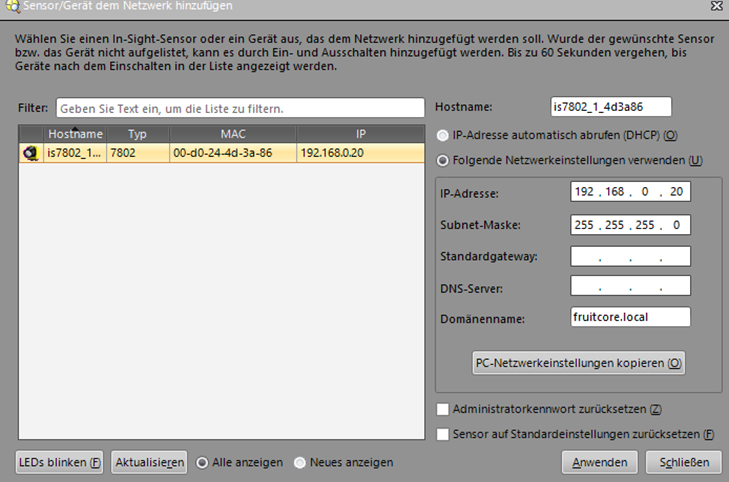
2.1 Installation of the camera and configuration in In-Sight Explorer
Using EasyBuilder, you can configure the camera in the In-Sight Explorer software. To do this, you need to create a new job under the "Connect" menu. The camera should be in offline mode for this configuration.
2.1.1 Triggering the Camera
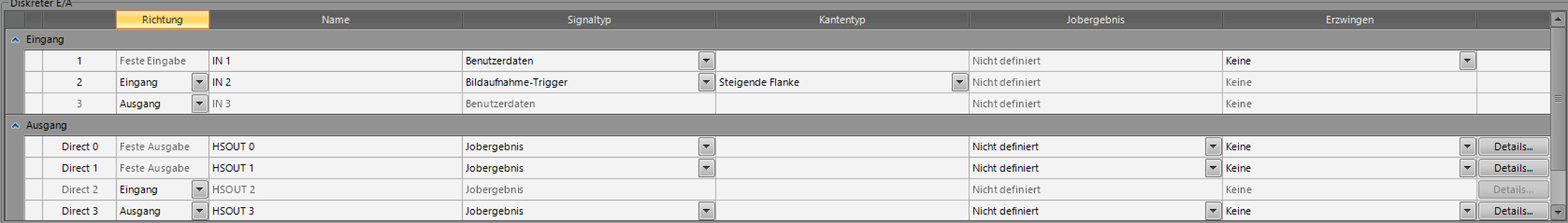
In the "Image Setup" menu, you can adjust basic recording settings. If you want the trigger to be digital, you need to select "External" in the "Trigger" field. Next, you must configure an input under the "Inputs/Outputs" menu so that the image capture trigger is activated when there is a rising edge.
2.1.2. Teach-in part
Within the "Part search" and "Part teach" menus, you can easily teach the desired objects. More information on this can be found in the EasyBuilder or In-Sight Explorer help guides.
2.1.3. Setting up communication
To configure communication between the camera and the robot, you can use the "Communication" menu.
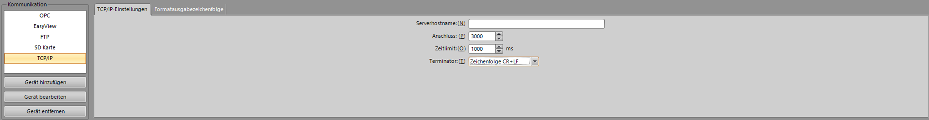
To set up TCP/IP communication with the robot, start by adding the protocol under the "Add Device" button. Choose "Other" under "Device" and select "TCP/IP" under "Protocol."
If the "Server hostname" field is left blank, the camera acts as a server. If a hostname is entered, the camera takes on the role of the client. Enter the port number under "Port," ensuring it matches the server or client's port number for establishing a connection via a socket.
In the communication setup, the camera can either act as a server or a client depending on the configuration.
The "Format output string" defines how the camera sends the results as a message over the socket to other participants. In the following setup, the format string is configured to output the object score, X and Y values, and object orientation. These values are separated by semicolons, making it easy to separate and assign them in horstFX later on.

2.2. Configuration of the camera using a spreadsheet
Using a spreadsheet, the camera can be configured as an alternative to the EasyBuilder in the In-Sight Explorer. While this method may require a bit more familiarity, it offers greater possibilities compared to the EasyBuilder.
To access the table view, simply right-click on the sensor in the network window.

2.2.1. Basic recording settings and triggering the camera
When creating a new project, an Image object is automatically generated in cell A0. By double-clicking on this cell, you can configure basic settings for capturing images. If the "Trigger Camera" option is selected in the dropdown menu, you can trigger a capture on the camera by wiring the digital trigger wire to the camera and setting a digital output on the robot.

2.2.2. Teach-in part
In the "Palette" window, you will find functions for controlling the camera that can be added to the table. Among the "Vision Tools," there are functions for object learning and verification. Simply drag and drop the desired action into the table and then double-click to configure it.

2.2.3. Setting up communication:
To set up communication via a TCP/IP Socket, start by adding a TCPDevice. You can find this in the Palette window under Input/Output ? Network ? TCPDevice. Once added, configure it by double-clicking on it. If the "Hostname" field is left empty, the camera will act as a server. The timeout setting in the Timeout field is not considered in this case. TCP/IP is selected as the protocol.

Next, add the "WriteDevice" action. You can find this under Input/Output ? Network. Configure this action as follows:
For the first argument "Event," select the cell number of the "Image" function, which is typically A0.
Assign the cell number of the device as the second argument. The device in this case is the TCPDevice you just added.
For the third argument, pass the cell number of the action that sends the desired data over the socket. To handle the scenario where the camera doesn't detect an object, include an if-condition. In this example, we check the quality. If the quality is not equal to 0, the message from the cell specified in the second argument of the if-condition is transmitted. In this case, we simply choose the empty cell next to the "WriteDevice" action. If the quality is equal to 0, we send this information - the cell where the quality is located (in this example G5) - as the third argument of the if-condition to the robot. This information informs the robot that no object has been detected.

In the selected empty cell above, we now add a function that includes the desired results of the camera detection to be sent to the robot via the socket. To do this, we use a "FormatString" action found under Text ? String. By double-clicking on this function, you can now configure it. You can select the desired detection parameters by clicking the "add" button. Using the delimiter, you can then easily separate the entire string sent over the socket on the robot.

3. Communication in horstFX
To communicate with the camera, the IP addresses of all participants must be within the same range. The process of changing the robot's IP address is detailed in the documentation on IP address modification.
Next, we will discuss communication using a digital trigger signal and TCP/IP via a socket.
To trigger the camera using a digital wire, follow the instructions in Section 2.1.1 on triggering the camera to set up the digital input on the camera. Once correctly wired with the "digital out" terminal in the robot's control cabinet, the camera can be triggered by activating the corresponding digital output.
// Trigger the camera using a digital output signal (edge-triggered)
output_literal( "OUTPUT_2", 1.0 );
sleep(100);
output_literal( "OUTPUT_2", 0.0 );
The object coordinates are sent to the robot using TCP/IP sockets. For more detailed information on communication via TCP/IP sockets, refer to the documentation on Sockets.
3.1. Establishing the connection via a socket
var IP_Cam = "192.168.0.20";
var Port_Cam = 3000;

var socket = new java.net.Socket();
socket.connect(new java.net.InetSocketAddress(IP_Cam, Port_Cam),  10000); // 10 s timeout
A timeout can be set up in case the camera does not send a message for some time. This ensures that the program does not get stuck waiting for a message from the camera, allowing for smoother operation.
// Set a 10-second timeout for reading the message via a socket by using the command
socket.setSoTimeout(10000);
3.2. Reading the camera message via socket
The camera message can be read using the following function:
function readFromSocket() {
    var bufferedReader =
        new java.io.BufferedReader(
            new java.io.InputStreamReader(
                socket.getInputStream()));
    var charArrayType = Java.type("char[]");
    var buffer = new charArrayType(1000);
    try {
        var anzahlZeichen = bufferedReader.read(buffer, 0, 1000);
        var nachricht = new java.lang.String(buffer);
    } catch (e) {
        var nachricht = "Timeout: No message received.";
    }
    return nachricht;
}
The function can be called using the following line:
// Reading the camera message.
var Msg_Cam = readFromSocket();
show_info(Msg_Cam);
3.3. Splitting the camera message
The camera message can be split using the following lines of code. The message and its splitting are related to the format string defined in section 2.1.3 for setting up communication.
// Splitting the camera message
Msg_Cam = Msg_Cam.split(";");
var Cam_Score = parseFloat(Msg_Cam[0]);
var Cam_X = parseFloat(Msg_Cam[1]);
var Cam_Y = parseFloat(Msg_Cam[2]);
var Cam_rz = parseFloat(Msg_Cam[3]);

show_info(Cam_Score + "\n" + Cam_X + "\n" + Cam_Y + "\n" + Cam_rz);
4. Complete Example Program
The following program is a simple example illustrating the communication between the robot and the camera.
var IP_Cam = "192.168.0.20";    // IP Adresse der Kamera
var Port_Cam = 3000;        // Port der Kamera

// Establishing a connection via a socket
var socket = new java.net.Socket();
socket.connect(new java.net.InetSocketAddress(IP_Cam, Port_Cam),  10000); // 10 s timeout
// Set a 10-second timeout for reading the message via a socket.
socket.setSoTimeout(10000);

// Program Flow:
try
{
    while(true)
    {
        // Move the robot to the capture position.
        move({
                'Coord': 'CARTESIAN_BASIS',
                'MoveType': 'JOINT',
                'PoseRelation': 'ABSOLUTE',
                'anyconfiguration': false,
                'speed.ratio': 1.0,
                'target': {'xyz+quat': [0.421058, 0.296112, 0.555801, -0.000097, 0.548429, -0.836197, -0.000003]},
                'tool': 'No Tool'
        }, "Capture position");

        // Trigger the camera using a digital output signal (edge-triggered)
         output_literal( "OUTPUT_1", 1.0 );
          sleep(100);
        output_literal( "OUTPUT_1", 0.0 );

        // Reading the camera message
        var Msg_Cam = readFromSocket();

        // Check if the object has been detected.
        if((parseFloat(Msg_Cam) != 0.000) && (Msg_Cam != "Timeout: No message received."))
        {
            // Splitting the camera message
            Msg_Cam = Msg_Cam.split(";");
            var Cam_Score = parseFloat(Msg_Cam[0]);
            var Cam_X = parseFloat(Msg_Cam[1]);
            var Cam_Y = parseFloat(Msg_Cam[2]);
            var Cam_rz = parseFloat(Msg_Cam[3]);

            show_info("Score: " + Cam_Score + "\n" + "X: " + Cam_X + "\n" + "Y: " + Cam_Y + "\n" + "rz: " + Cam_rz);
        }
        else if(Msg_Cam == "Timeout: No message received.")
        {
            show_info(MSG_Cam);
        }
        else
        {
            show_info("No object detected by the camera.");
        }
    }
} finally {
    socket.close();
}

// ******************************************* Functions*******************************************

function readFromSocket() {
    var bufferedReader =
        new java.io.BufferedReader(
            new java.io.InputStreamReader(
                socket.getInputStream()));
    var charArrayType = Java.type("char[]");
    var buffer = new charArrayType(1000);
    try {
        var anzahlZeichen = bufferedReader.read(buffer, 0, 1000);
        var nachricht = new java.lang.String(buffer);
    } catch (e) {
        var nachricht = "Timeout: No message received.";
    }
    return nachricht;
}