The PLOC2D from SICK is a vision system for 2D part localization. The camera offers an easy-to-use web interface and can locate parts quickly and reliably without external computing capacity.
1. Introduction
The sensor system can either be permanently mounted next to the robot or mounted directly on the flange of the robot using a suitable bracket. In the following article, the sensor system is set up and calibrated. Subsequently, a part localization with gear wheels is carried out.
For more information about the SICK PLOC2D camera, see SICK user information.
2. Installation of the SICK PLOC2D
2.1 Camera installation
New cameras have the IP 192.168.0.1 by default, but this can be adjusted later in the settings. DHCP must be deactivated!
As soon as the laptop and the camera are in the same network, the camera can be accessed via a web interface.
2.2 Calibrating the camera
First, the user should be changed to "Service". Only this user can teach in new objects and calibrate the camera.
The user can be changed at the top right.
For service, the password is "servicelevel".
The first images for testing can then be taken in the Installation menu item.
An alignment laser can also be added here for positioning. Exposure time, brightness and contrast can also be set.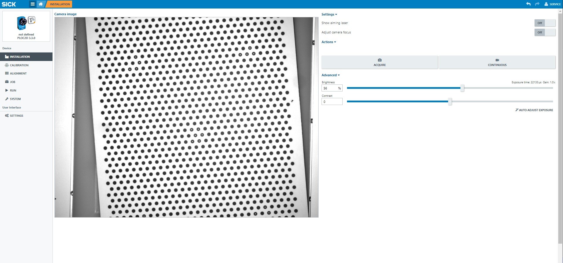
Once the camera is properly aligned, it needs to be calibrated. To do this, navigate to the calibration menu.

To calibrate the camera, a CalibrationTarget is required, which comes in different sizes.
Select the appropriate size in the top right corner. Additionally, specify the camera's focal length.
To get a good estimation of the camera, it is recommended to capture at least 10 images.
Click on "Capture Image" to take the first image for calibration.
Afterwards, a similar image should appear.

After capturing each image, it is important to slightly move and rotate the CalibrationTarget.
Click on "Capture Image" to take a second image for calibration.
Afterwards, a similar image should appear.

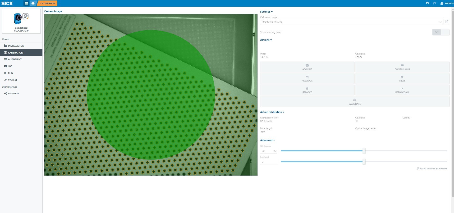
The small rectangles become greener and more filled with each captured image.
The process should be repeated until no rectangles are visible.
The resulting image should look similar to the following example.
Even if the coverage area is at 100%, the circle is completely green, and no rectangles are visible, it is still recommended to capture at least 10 images for accurate calibration.
Clicking on "Calibrate" will complete the process.
Depending on the number of images captured, the camera takes approximately 1 minute to calculate the calibration.
2.3. Alignment
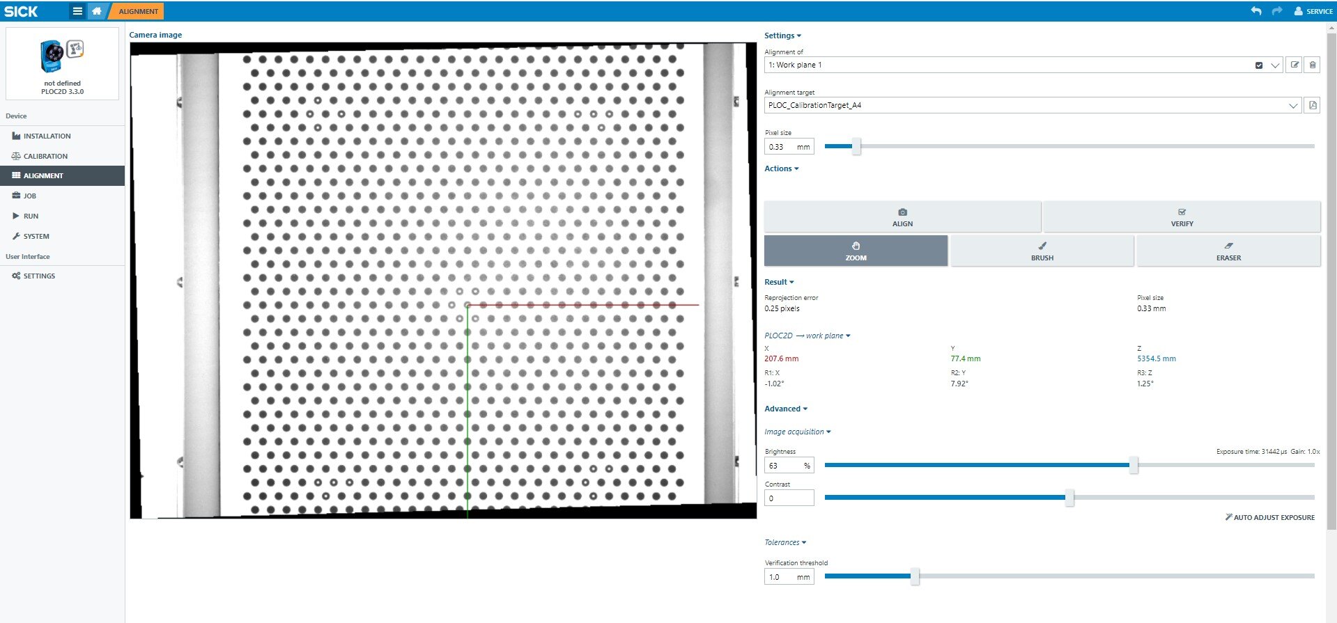
Navigate to the "Alignment" section on the web interface of the SICK PLOC2D.
In this step, you will determine the reference coordinate system. To maximize the field of view, it is recommended to position the calibration plate under the camera without any rotation.
Click on the "Align" button to perform the alignment process.
If the image appears to be heavily distorted, you can repeat this step as needed.
Afterwards, the robot should move its TCP to the reference point.
This point is marked by the red-green coordinate system.
Remember to save this position as it will be used later for object position estimation.
The image below is an example of what not to do. If your calibration plate looks like this, it means it needs to be rotated.

3. Teach-in objects
New items can be taught in under the "Job" menu item.
First select a job in the top right-hand corner. A job corresponds to an object.
To do this, place the object to be recognized in the camera's field of view and then take a picture using the "Take picture" button.
Make sure that the values for lighting time, contrast and brightness are transferred here from the settings at the beginning, as this is not done automatically.
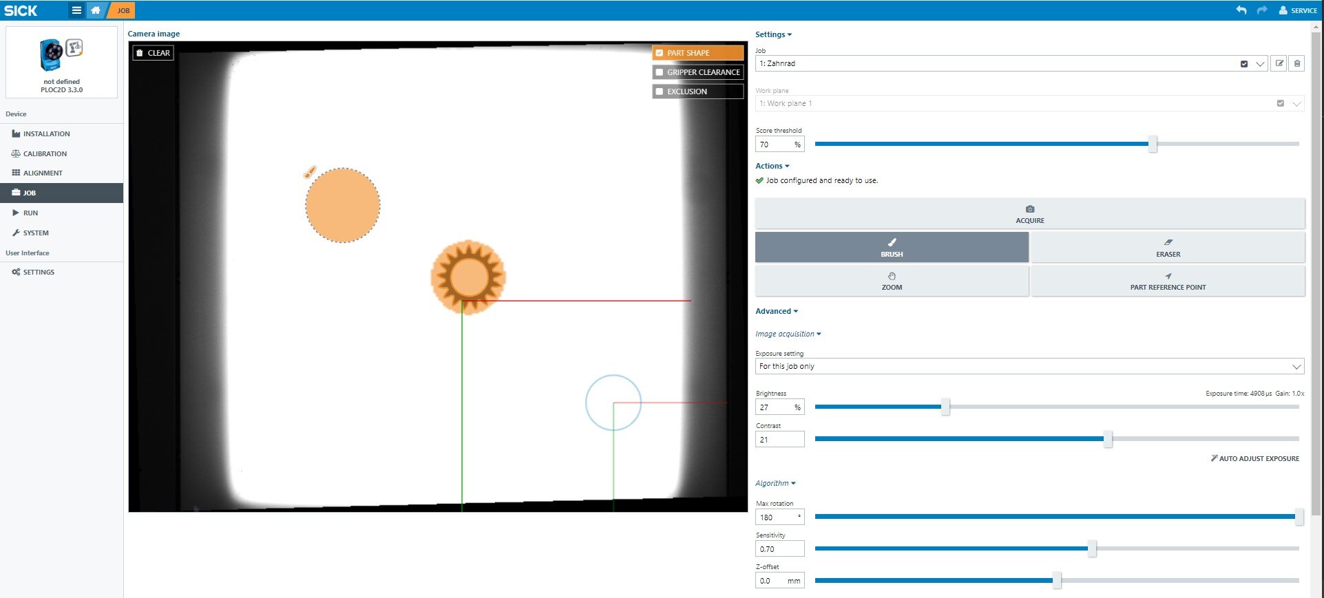
Once you are happy with the settings, you can select the area that is to be recognized later. To do this, press the "Brush" button and then select the area.
The web interface sometimes reacts a little slowly, so wait until the brush has actually been selected (the same applies to the eraser, zoom and the "Object reference position").
When marking, it is important to ensure that no reflections are marked. These are not the same on every object and in every place. You should also choose edges that are clearly recognizable and easy to distinguish. You can zoom in on the object for more precise marking.
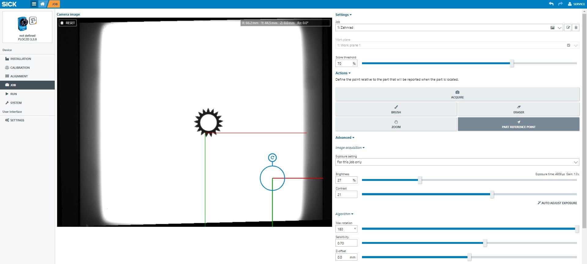
The transparent orange area shows the area that has been marked. The orange lines show the edges that will later be used for recognition. (Area of the sample part)
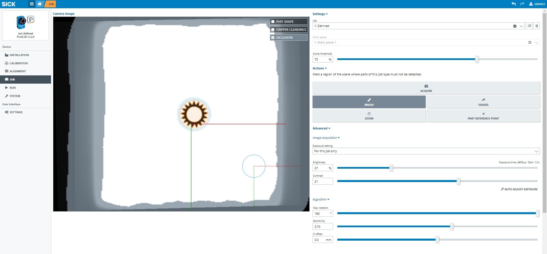
The gripper clearance can then be taught in; this works in a similar way to teaching in the area of the pattern piece. The inner contour can be removed with the eraser (see image below).
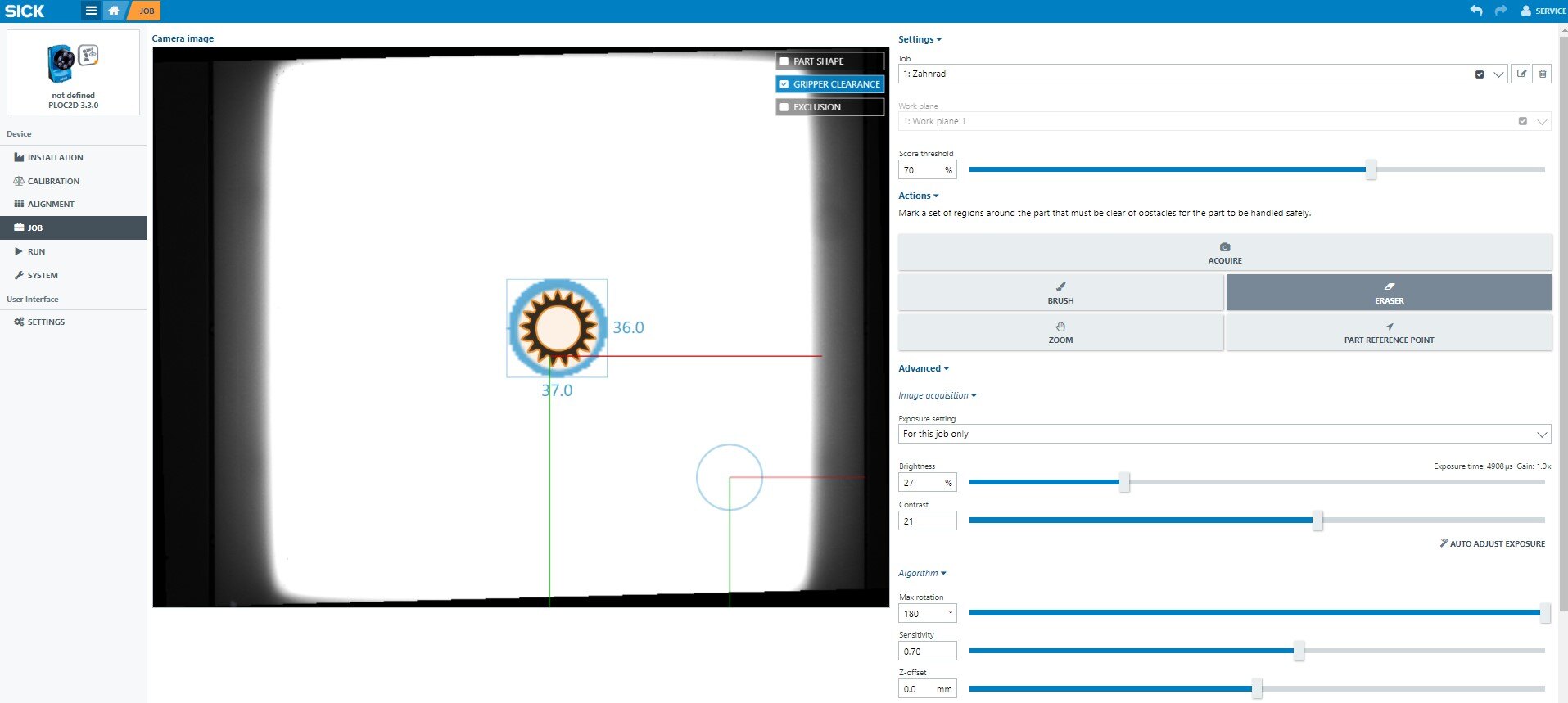
This area can be defined as blocked so that parts at the edge are not gripped.
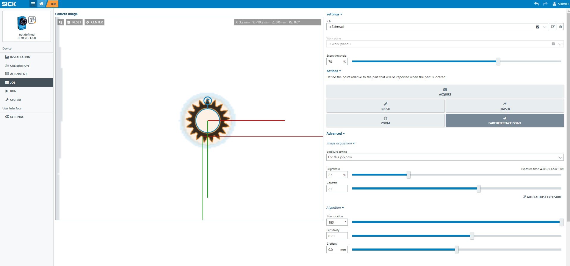
In the next step, the "Object reference position" must be set. This position will be sent to the robot later. The reference position should therefore be placed as centrally as possible within the object. The orientation results from the contour of the component (in the example there is no orientation, therefore the lines are parallel to the global coordinate system)
Finally, a threshold value can be set. This specifies the required match for valid detection.
The value must be determined experimentally, as it depends heavily on the background, exposure, the object and other factors.
4. Testing
In the "Run" menu, you can test the system.
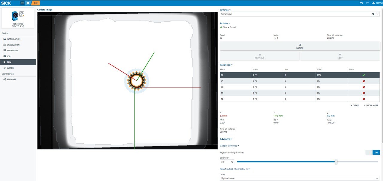
Select the object that you want to be recognized by clicking on it in the top right corner.
After clicking on "Locate", a picture will be taken and all the objects that were previously selected will be searched for in the image.
You can use the "Previous" and "Next" buttons to view the different objects if more than one is detected.
The table in the "Log" section shows the results.
From left to right, it displays the recognized object, the detection time, the estimated match, the X and Y displacement, and the rotation angle of the object.
Feel free to experiment with different settings to achieve the best results.
5. Camera Control
The camera communicates directly over TCP/IP by sending individual packages.
The content must be in XML or CSV format.
Once the camera has been properly calibrated, only two commands are required for object detection.
5.1. Run.Locate, [Job number]
To capture a new image and locate the parts from the specified job, follow these steps.
In the following examples, objects (jobs) 1 and 3 will be recognized.
5.1.1. XML-Example
<message><name>Run.Locate</name><job>1 3</job></message>
5.1.2. CSV-Example
Run.Locate,1 3
5.2. Run.Locate, [Job number],[Match]
This command returns a result from the previous Run.Locate command. The specific result to be returned is determined by the "Match" parameter.
In this example, the second detected object from object "3" will be returned.
5.2.1. XML-Example
<message><name>Run.Locate</name><job>3</job><match>2</match></message>
5.2.2. CSV-Example
Run.Locate,3,2
Additional commands can be found in the Quickstart guide for the PLOC2D camera.
5.3. Example program
The attached program shows a simple example of how to communicate with the camera.
The most basic functions for communicating with the sensor system from horstFX are explained below.
5.3.1. Establishing a connection to the sensor system
A connection from horstFX to a PLOC2D is established via a socket. Depending on how the network is set up, the IP address and port may need to be adjusted.
function initCamera() {
    return new java.net.Socket("192.168.0.10", 14158);
}
5.3.2. Send data to the sensor system
Data can be sent to the sensor system via a PrintWriter, for example to generate a new image and evaluate it.
function writeToSocket(nachricht) {
     var printWriter =
          new java.io.PrintWriter(
               new java.io.OutputStreamWriter(
                    socket.getOutputStream()));
     printWriter.print(nachricht);
     printWriter.flush();
}

writeToSocket("Run.Locate,1");
5.3.3. Read data from the sensor system
Data from the sensor system can be read using a BufferedReader. The sensor system sends the data as a string, which can then be processed further as needed. In this code snippet, the data is displayed as an information message on the PANEL.
function readFromSocket() {
     var bufferedReader =
          new java.io.BufferedReader(
               new java.io.InputStreamReader(
                    socket.getInputStream()));
     var charArrayType = Java.type("char[]");
     var buffer = new charArrayType(1000);
     var anzahlZeichen = bufferedReader.read(buffer, 0, 1000);
     var nachricht = new java.lang.String(buffer);
     return nachricht;
}

var cam_result = readFromSocket();

show_info(cam_result);
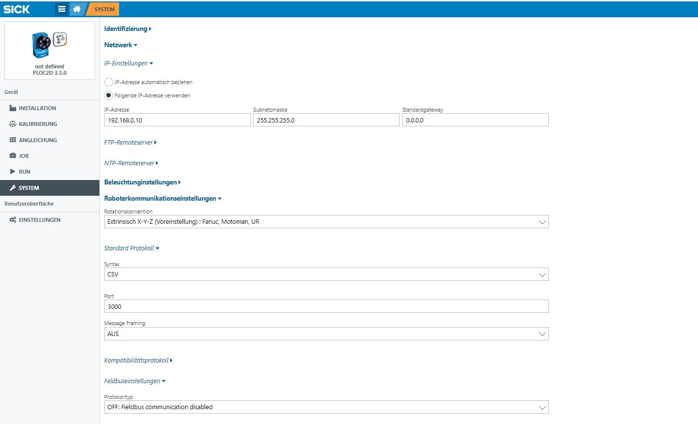
5.4 Camera Settings
Here is an example of how to configure the IP address and robot communication settings on the SICK PLOC2D camera. The CSV protocol was used for this purpose.
6. Download Files
Please click on the file name to initiate the download.
Textual Basic Program:
Graphical Basic Program for Software Version 2023.11:
SICK Vision horstFX-graphical Software 23.11
7. Important note
- If you want to use the provided files as a basis for your own program, you should adopt the input/output labels from the configuration file: "PartSeparation_2311_public_2.io". This file is located in the ioconfig folder. For fruitcore robotics products, these labels are already set by default.

- "The 'Locate' command only provides the difference from the position that was approached in the Alignment section.
- It is important to consider that the coordinate systems of the camera and the robot may be rotated when adding the difference.
- The camera does not provide the height information. The height needs to be manually approached or slowly approximated beforehand."