This article describes how to integrate, configure and connect the PLC and the robot in the Siemens TIA Portal.
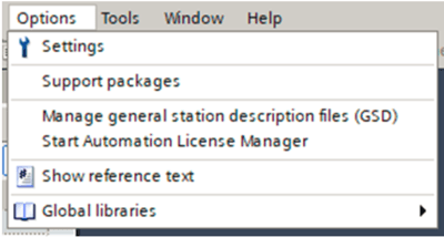
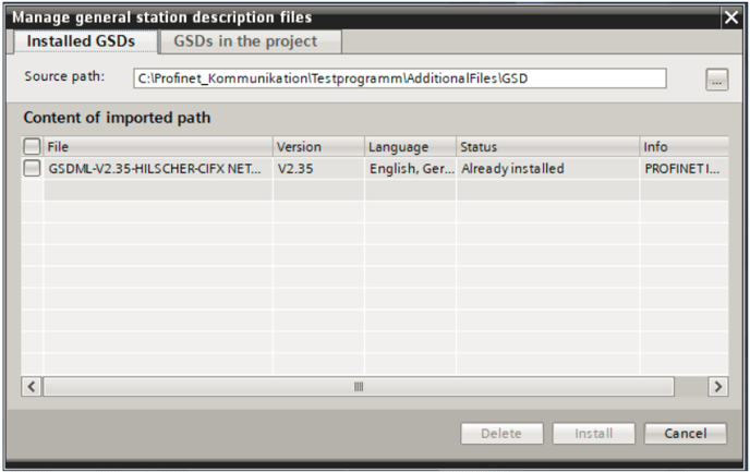
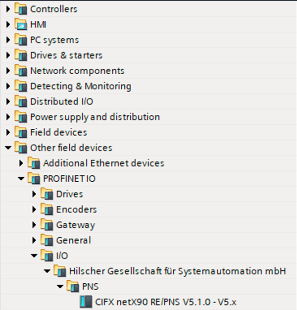
1. Adding the device description file
2. Creating the Profinet modules
The data is transferred in individual modules from the PLC to the robot. For this, the modules are selected on the right in the hardware catalog and dragged into the device overview via drag-and-drop. It is possible to choose between input and output modules of different sizes.

For the communication with the robot 11 input modules and 10 output modules with a size of 64 bytes are used. therefor the first 64-byte input register is pulled into Slot 1. Then the remaining 10 input registers follow. The 64-byte output registers are placed on the Slots 12 - 22. The following figure shows the correct arrangement of the modules:

3. Configure and download the device configuration
When all modules are added, the IP address of the network and the Profinet device name of the robot are set in the device settings. Please regard that both devices (CPU) and robot are in the same range of the IP address (first 3 ranges identical, last range different).
Via a double click on the network interface of the device you reach the setting of the desired parameters.
When the device settings are completed, you switch back to the network view. There now the PLC, which was added before as a new device (with corresponding CPU), is connected with the robot. For this, the network interface of the first device is clicked and dragged into the network interface of the second device. The TIA Portal then connects the two devices, which is represented by the green connection line shown below.

Afterwards the hardware configuration can be downloaded to the PLC. To do this, select the PLC with a right-click and select "Download to device" ? "Hardware configuration" in the context menu.
The last step is to assign the device name of the robot. This is done by right-clicking on the robot, then selecting "Assign device name" in the context menu. A window opens in which the connected devices are searched. If the desired device is displayed, select it and click on the "Assign name" button.
4. Import robot data types into the TIA Portal
For the communication with the robot special data types are created, in which the different registers are created. These data types are described in more detail under the following links: Output data/ Input data. To be able to use the registers, two data types have been created. One data type for the data that is sent from the PLC to the robot ? "Outputs" and one data type for the data that is transferred from the robot to the PLC ?" Input".
To import the data types, a PLC (CPU) must first be added. Then the tab "External sources" is opened in the project navigation on the left and "Add new external file" is clicked. Thereupon a window is opened in which the two data types are selected and opened. The required UDT files can be found in the appendix.

After opening, the selected data type appears under the "External source files" tab. If you select this data type with a right click, a context menu appears in which "Generate block from source" is selected. Thereupon four data types are added to the project, this appears in the tab "PLC data types".

Now a variable table is inserted in the project navigation under "PLC variables" and a variable for the input data and one for the output data is created there. For this the variable name is assigned and the data type "HORST_Input" or "HORST_Output" is selected. When adding the modules in the previous chapter, an input or output address was assigned for each module. For the data type "HORST_Input" the address of the first input module is selected. Similarly for "HORST_Output" the address of the first output module is selected. In this example the first input address = %I68 and the first output address %Q64. Once the two variables have been created, they can be expanded and the individual registers and their associated memory address appear automatically. Via this address the registers can now be used in the program blocks and data can be exchanged between PLC and robot.

5. Appendix
The two attached files contain the device description file for integrating the robot as well as the data types for transferring the input and output data.
UDT till horstFX-Version 2021.10
UDT valid from horstFX-Version 2022.01